RSP Spectrum Analyser
Tracking generator
The analyser includes the facility to control an external signal source in conjunction with a Arduino Uno module so that a fully synchronised tracking generator may be realised. For the tracking generator, support is offered for the Analogue Devices AD9850 and AD9851 direct digital synthesisers, as well as the Skyworks Solutions SI5351A clock generator.
Firmware for the AD9850, AD9851 and the SI5351A clock generator is contained in a single HEX file and generator module selection is made by linking two port pins on the Arduino Uno. Currently only a single output is used with the SI5351A clock generator, although it is capable of generating three different frequencies simultaneously. Future development of the analyser may make use of this feature so that signals may be fed to an external mixer in order to obtain higher frequencies than the current maximum of around 160MHz.
Additional support is offered for the GRA-AFCH AD9910 DDS module which includes accurate output level control with a maximum frequency of 400MHz, or 600MHz with overclocking and a heat-sink. In addition AM and FM modulation facilities are provided thus providing a very useful signal generator. The firmware provided by GRA & AFCH has been modified so that the analyser can take control of the module for use as a tracking generator, leaving the original code intact should the user choose to use the generator for other purposes. When the generator is connected to the analyser, all modulation functions and signal level control are still functional and are controlled by the analyser. Further information can obtained at RF Units - GRA & AFCH
Facilities are also offered to allow the user to communicate with, and control their own custom-built tracking generator using a simple command structure over a serial link. The command structure is fully documented in the analyser's use manual. This is useful if the user has some form of signal source that requires a serial, USB or GPIB control input. The user will be required to write their own code, either running on an external processor of their choice via a serial link, or communicating with software running on a PC.
There is a free application available on the Spectrum Analyser Facebook page in the Files areas called VirtualTrackGen.zip. The ZIP file includes an executable file of the demonstration application, as well as full source code, and a user manual. The Virtual Trackgen demonstration code has been written to illustrate how the analyser communicates with an external generator, and provides enough information to allow you to write your own driver code to control a generator module not currently supported by the analyser, or perhaps a separate signal generator that can be controlled via a serial link or GPIB interface, or even your own home-brewed system
Communication with user-written code running on the same PC as the analyser may be established by using virtual serial ports. Several free virtual port systems are available. Eterlogic offers a free version of their VSPE (Virtual Serial Port Emulator). VSPE can create virtual serial ports in a range of configurations as well as offering Tcp Server, Tcp Client, UDP manager support and several other useful features in the same application.
See Virtual Serial Port Emulator at at Eterlogic for for further details and a free download.The Arduino IDE does not include the facility to upload a HEX file to a target board directly. It can be done by using the command line interface to AVRdude. There is a far easier way to upload hex files to your Arduino board. Xloader is an application developed for uploading HEX files to a target board without having to get involved with the complexities of the AVRdude command line interface. Xloader can be downloaded from Github at this link: Github Xload page There is a full set of instructions for installation and use on the page. Click on the green Code button at the top of the Github page and select Download ZIP. Unzip the files into a folder and double-click on Xload.exe, no other installation is required.

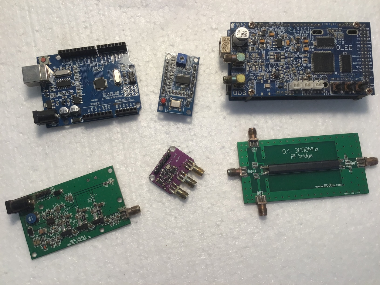
This image shows a range of modules that you may use to build your tracking generator. They are the Arduino Uno, an AD9851 (or an AD9850) DDS module, the AD9910 module from GRA-AFCH, a noise generator, the Skyworks Solutions SI5351A clock generator and an RF return loss bridge. A minimal setup can utilised by using a noise generator on it's own, and optionally the RF return loss bridge.
A fully synchronised tracking generator will require the Arduino Uno and either the AD9850 (or a AD9851) DDS module, or a Skyworks Solutions SI5351A clock generator module, or the GRA-AFCH,AD9910 module. That module will also require an Arduino Mega2560 in addition, although it can be ordered with the Mega2560 included. The GRA-AFCH AD9910 module does include a small OLED display screen but is not shown in this image.